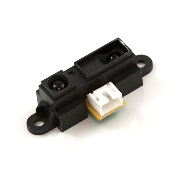
Today I will be linearizing a Sharp IR Ranger. More specifically, I will be using the Sharp 2YOA21 F 04.
First, a quick word on why we would want to do this. The Sharp ir rangers are a very effective means of measuring distance. While ultrasonic sensors (for more about those see the Sensors label) can be fooled by textures and echos, ir sensors are more susceptible to interference from outside light sources and changes in material reflectivity. Therefore, if a cheap measurement system is required in a varying environment (eg, a mobile robot) a combination of ultrasonic rangers and ir rangers can be quite effective.
If you have found this page, you probably already know this, but I will state it anyway. Sharp ir sensors have an analog output. However, the analog value does not have a linear relationship to distance. In this exercise we will find the function that does relate the two and use that to take an analog value and convert it to a distance.
Wiring
As stated above, the sensor has an analog output. Connect the red lead to +5V, black lead to GND, and yellow lead to A0.
Aquire Data
I used a simple sketch that took the average of 5 values and printed it to the screen. I then manually copied it into an excel spreadsheet along with the measured distance value.
Once you have acquired the data, plot it. Some points will most likely fall outside of the trend. Exclude those points and fit the rest. My fit was Value = 1893.9*Distance^-0.92.
Use Equation
Solving the equation I got above for Distance gets me this, Distance = (1893.9*Value) ^-1.087.
This is something we can plug into Arduino code. At this point it is only right to note that the method I am using will involve floating point math. There are methods that avoid that. If processing power is at a premium, you might want to check those out.
The other day I was starting up my computer in a rush before class. As I waited for all the "necessary" startup programs to start up, it hit me. Wouldn't it be great to be able to a prioritize the way my computer starts up? More than that though, I want to be able to tell some programs to not launch until my computer isn't being used. They can load up after I leave for class. If I need them I can just launch them manually.
A few Google searches yielded a few programs (some free some not), but I am always hesitant to hand over important things like startup procedures to an unknown program from the abyss. Then I found my answer.
Enter Window Task Scheduler. I had encountered Windows Task Scheduler before on Windows 8 but hadn't ever directly used it on Windows 7. It does exactly what I wanted! Using the task scheduler it is pretty trivial to create a task to start a program after startup and whenever the computer is idle. However, I thought I could make it easier.
I decided to create a batch file to launch my secondary programs (KeePass, iTunes updater, etc.). Then all I have to do is create one scheduled event in the task scheduler to launch the batch file. Even better, I can put the batch file somewhere convenient (the desktop, documents, etc), so it is easy to change. If you're reading this, I will assume you know how to find the startup programs you have on your computer. Make sure you don't get delay an important one.
Anyway, here is the batch file code. The best way to see what is going on is to just open a command window and type HELP START. This will give you all the commands you need. Note that if you are using a location that has spaces you will need to put it in quotes with a /D preceding it.
And here are some screenshots of me making my scheduled event.
Create New Task
Adding a Trigger
Triggers for My Event
Adding Action to be Triggered - Launch Batch File
Hopefully this is useful to someone. As my Calculus II professor always said, "What is that American expression? There is more than one way to skin the cat?" If I missed a much easier, more effecient, or more logical one feel free to comment. This just seems to work for me.
This was a quick afternoon project that I worked on a few weeks ago. The beginnings were pretty simple. I was digging through the basement and found an old 12v cordless drill whose batteries had died. Being me, I decided that it would be cool and pretty easy to connect a cord to it and plug it into a lab power supply or other 12V source.
As this project is pretty dependent on the type of drill you have, I will try to include what pictures I took. Also, it is worth noting that as I type this Walmart has plenty of decent corded and even cordless drills for less than $40.
Step 1)
Take apart the battery. Determine the positive and negative leads. On mine white = negative, black = positive (similar to wiring a house).
Step 2)
Aquire a cord. The wire I scavenged is suspected to have come off of an old vacuum. I would recommend scavenging for this project to keep costs down. I also found some banana plugs to make it easier to connect to a power supply. I considered using some old test lead alligators.
The kind of Banana Jack I used
Step 3)
Remove the batteries and wire together. I actually left some of the batteries in the casing to add some counterbalance. I then soldered on the wire, punched a hole in the case to let the wire out, and hot glued everything together.
Step 4)
Test. My next step was to hook it up to a car battery and test it. It worked! for a few seconds. Then the burnt smell.
The drill did not like being run on a car battery. There is a large diode inside the drill that I burnt out. Luckily, I found a replacement in a box of old hairdryers that we happened to have on hand.
With the replacement diode in, I took it over to a lab and tried it out. It worked fine. There was still a slight burning smell, but I suspect that may just be dust in the motor from years of non use. Overall it seemed to work ok. The video below will give you a peak at the power supply readout during testing.
Some might call this a wasted Saturday afternoon, and they are probably right. However, if you enjoy tinkering with things, making a corded cordless drill might be right up your alley.
This is my first "reader requested" post. A reader sent me an email asking me to do a post about controlling a stepper motor using a shift register, and here it is. In this post I will specifically discuss controlling a 28BYJ-48 stepper motor with a 74HC595 shift register, ULN2003, and Arduino.
First of all, I need to explain what a shift register is. Rather than doing that however, I will differ you to THIS page. It does an excellent job of introducing shift registers and provides some really easy to use sample Arduino code. My code is based off of the functions on that page. I will be using a 74HC595 shift register. I chose it because it is pretty common. I got mine off of eBay, but you can buy them at various vendors.
Second, I should point you to some information on the stepper motor I will be using. It is a 28BYJ-48 stepper motor. It is the same one I used in the two posts(Arduino Control and ATtiny Control). If you need it, those two pages have links to some good reference material.
Third, like in the other cases, I will be using a ULN2003 to drive the stepper. This is pretty common with this board. However, this time I just wired it up on my breadboard rather than using the control board that came with my stepper. I did this because I intended to solder together a whole control board. In the end, I decided I didn't have a need for it at the moment and just left it breadboarded. I can always solder it later.
Now, wiring this project has a few more wires than some of my others, so I threw out all the stops and made a Fritzing schematic. When you look at it, wiring is not terribly complicated; the wires just get crossed easily.
So here is what is going on. The Arduino is controlling the shift register like described in the link I provided above. The shift register outputs are fed into the ULN2003. The ULN2003 acts as a switch and allows the stepper to draw the current that it needs to operate.
One thing you may wish to change, in this diagram I have the stepper being driven by the 5V from the Arduino. It may be wise to drive it from an external 5V source if you are doing more than one. Also, the colors on the stepper (or even the order of the wires) can vary from vendor to vendor. Basically, if the stepper just sits there and grinds against itself, switch the wires.
Another thing that confused me for a little while, the ULN2003 sinks current (as opposed to sourcing current). That is, it allows the output to be a path to ground if the input is HIGH. If you wire the stepper like shown above it should work. The trouble comes when people like me want to test it with an LED before connecting the stepper. I connected the positive end to the ULN2003 and the negative to ground. Eventually, I realized my mistake and switched it. Long story short, to test with an LED, put the "negative" end on the ULN2003 output and the "positive" on 5V.
Here is my setup for this project. The sketch I used is an adaption of one of the sketches from my previous posts. Basically, where there was a digitalWrite I put a setRegisterPin. A potentiometer controls the speed. Get my code HERE.
The motor did not turn very quickly (around 10 seconds a revolution), I suppose I shouldn't have expected much more considering all the delays the shift register puts into the system, but if you ever needed to control a large number of stepper motors on only a few pins maybe this would be an option. If you do plan on that, you might note that the ULN2003 only has 7 inputs/outputs, so be sure to get the right number of parts.
Also, it appears that this sketch could very easily be wrapped into a library. Perhaps the stepper library could be edited to utilize a shift register. Regardless, that is beyond the scope of this post. I leave that to the reader (though feel free to tell us about it in comments).
Hopefully this is useful to someone. If anyone else has suggestions for posts, let me know. The reader requested label is looking pretty lonely.
Recently I got my DHT11 temperature and humidity sensor working with my Arduino Mega2560. If you are interested in that, check it out HERE. However, while that was all well and good, I found it a bit impractical. While I may someday decide to create some sort of weather logger using the DHT11, it is unlikely that I would dedicate an entire Arduino to the task. Enter ATtiny85.
The ATtiny85 is great because it is cheap, but the real question is, "Does it work with the DHT11?" Yes it does.
Now in my last post I used the DHT library from Adafruit. While that library served its purpose, it does not work with the ATtiny. Don't ask me why; I did not explore it. HERE is another report of it not working and a description of what will happen if you try it. It reads out all zeros.
What does work is the DHT11 library. To get it working you will need to modify the example code. Basically, you need to change everything that says "Serial" to the Software Serial equivalent. This will allow us to get the sensor readings back from the ATtiny. If you want more information on serial communication on an ATtiny, check out THIS post. Alternatively, you could just download my code (HERE), wire everything the way I say, and see if it works.
Now when you go to compile my example, there is a good chance you will run into a problem. As it turns out, there is an issue with the tiny core when trying to compile sketches close to the maximum sketch size. Luckily there is a quick and easy fix. I won't go into the details, but follow the instructions HERE.
When that was straightened out I was able to upload my sketch successfully. I used my USBtinyISP and my ATtiny85/45 programming adapter.
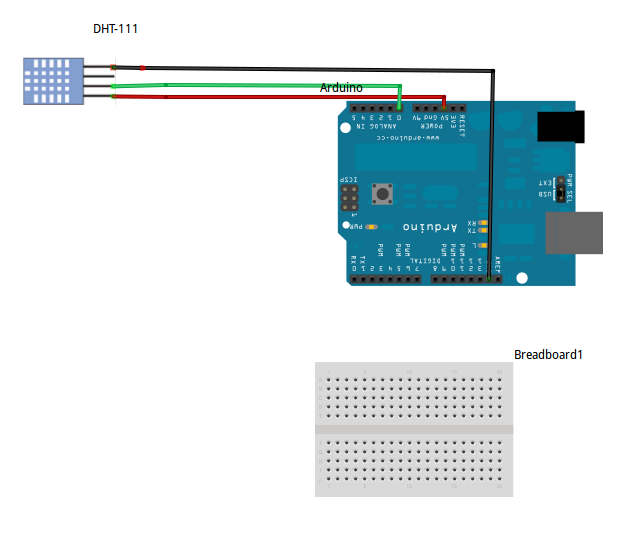
The only thing left to do is wire it up and see the output. Basic wiring of the DHT11 is the same as in my last post.
Correct Wiring: Pin 1: +5V Pin 2: Signal. Connect to digital IO with a 5k ohm pull-up resistor Pin 3: Nothing. Some people suggest grounding it if you run into trouble Pin 4: GND
On the ATtiny side, PB3 is the software serial Rx and PB4 is the software serial Tx. Connect those to an FTDI (or some other serial receiving device). Connect 5V and ground.
Power it up and watch the show!
This of course could be modified to do other things with the temperature data. It could, for instance, transmit them via I2C. Maybe it could log them on an SD card. Those projects I leave to you (for now anyway). If you are interested in more ATtiny projects of mine, check out my ATtiny label. Let me know if this works or doesn't work for you. As always, I'm happy to help.
In this post I will be playing with the DHT11 Temperature and Humidity Sensor with my Arduino Mega 2560. While a DHT22 could also be used, I used a DHT11 mostly because it and it was cheap. I think I got mine for around a dollar. They can also be found it premade breakouts, but there really isn't much to them. As you can tell from the picture in the link, the breakout merely removes the extra pin and adds the pull-up resistor and a decoupling capacitor.
Once you decide on which sensor to buy, you will be faced with yet another choice. What library should I use? There are approximately a lot of them out there. I chose the Adafruit DHT library found HERE. It worked for me (and supports multiple sensors), so I saw little reason to pursue any of the other libraries.
This does NOTwork
Now when I bought my DHT11 from Ebay, a picture like this was on the listing. Quite frankly, I don't understand what this is getting at. It doesn't work. While I can't vouch for the rest of the world, my sensor is not analog. It is digital. You can even look at the datasheet.
Correct Wiring: Pin 1: +5V Pin 2: Signal. Connect to digital IO with a 5k ohm pull-up resistor Pin 3: Nothing. Some people suggest grounding it if you run into trouble Pin 4: GND
Once everything is wired up, open the example sketch. It does about everything I would want it to do, so there is not much to say. Uncomment the correct sensor and upload. Open the serial monitor and get testing.
There isn't much to say about this sensor. It is slow and probably not too accurate, but with the hard work of making the library already done, this sensor is incredibly easy to use. If you don't like my description of this sensor, there are many others out there at your disposal. If you do like it, I'm glad I could be of help.
Today I will be taking some time to briefly revisit stepper motors. Recently I have been trying to map out the boundaries of my ATtiny capabilities, and it occurred to me that I have never gotten my stepper motor working with one. Eager to fix that I broke out my ATtiny85 and my 28BYJ-48 Stepper motor and went to town.
First things first, I already did a post on the 28BYJ-48 with a ULN2003 motor controller for the Arduino (HERE) and won't repeat the information listed there. If you are having trouble getting the motor to work on an ATtiny85/45, I recommend you go back and check out my other post. It has lots of useful links and tips.
If you need instructions on getting the ATtiny running with the Arduino IDE, check out my ATtiny label. For this post I will be using the Arduino Tiny core from Google Code. It runs on Arduino 1.5. For the programmer I will be using a USBtinyISP with my ATtiny85/45 programming adapter.
This really turned out to be pretty straight forward. Using the same Small_Stepper.ino example from my last post, I changed the pins to the correct values and everything worked (get my ATtiny sketch HERE). The motor turned nicely. One note about wiring, you can't actually wire this stepper the way that you define it. There are comments about this in my sketch, but for those that don't download the sketch, reverse the 2 middle wires. If you don't reverse the 2 middle wires the motor will not turn in reverse. If you want a longer explanation as to why and a complicated fix, go to THIS forum post. I just reversed the wires.
Example: Stepper small_stepper(STEPS, 0, 2, 1, 3); implies that you connect ATtiny pins 0, 2, 1, and 3 to pins IN1, IN2, IN3, and IN4 respectively. For this motor you should connect ATtiny pins 0, 1, 2, and 3 to pins IN1, IN2, IN3, and IN4 respectively.
Since that was so easy, I decided to do something else as well. I made a stepper version of the Knob example. Some readers may know that such an example already exists in the Arduino IDE, but I wasn't happy with the way it worked with my motor. My sketch works a little differently. As you can see from the video below, as I turn the knob, the speed of the stepper changes. If you want the sketch, you can get it HERE.
There you have it. Controlling a stepper motor with an ATtiny85 is not only possible, it is easy. If you run into problems or use this post to great success, let me know. I hope this post turns out to be somewhat useful.
In this post I will show you how to cheaply make an I2C sonar sensor for your Arduino. This will be accomplished by making an I2C controller for an HC-SR04 sensor out of an ATtiny85 (or ATtiny45). Both the sensor and the microcontroller can be found online for a few dollars. Together these two parts can save you money while increasing functionality over premade solutions.
If you have not already done so, check out my previous post on a serial sonar sensor. It also discusses running the NewPing library on an ATtiny (my modified TinyNewPing library). I have also done a post on I2C communication. In fact, I even transmitted data from my PING sensor! Check it out HERE.
1) First off, we need an I2C library for your ATtiny. For this you have a few options, but I will only be using one of them. The regular Wire library will not work on the ATtiny side. However, thanks to some great work by Arduino users BroHogan and Rambo we do have the TinyWire library. The original library by BroHogan can be downloaded HERE. I have used the Master library from it, but for the Slave library I will be using a fork by Rambo. He added a bit more functionality including an onRequest and an onReceive function (which I use in my examples). Find his library HERE (download zip link is in the bottom right corner).
You will also need the ATtiny core for whatever Arduino IDE you are using. In the past I have used the core from High-Low Tech. Now however I prefer the Google Code core. A recent update allows ATtiny support with Arduino 1.5. Anyway, if you need more details on getting an ATtiny running see my previous posts linked above or click on the ATtiny label.
You need to burn your ATtiny85/45 to 8MHz. This is important for stable I2C communication (consider making my ATtiny programming adapter!). You also need my TinyNewPing library installed.
2) Wiring is simple. Connect the 5V from the Arduino to the VCC of the ATTiny and the PING sensor. Connect all the grounds together. Then connect the Trigger and Echo pins of the PING sensor together and to pin 3 (PB3) of the ATtiny85. Next connect the I2C wires. Connect the ATtiny SCL (PB2) to the Arduino SCL (Arduino Uno: A5 , Arduino Mega2560: 21 , Arduino Due: 21). Connect the ATtiny SDA (PB0) to the Arduino SDA (Arduino Uno: A4, Arduino Mega2560: 20 , Arduino Due: 20). Finally, and very importantly, connect 4.7k (on 5V) ohm pull-UP resistors to the SCL and SDA lines.
3) Now you have the libraries installed. Everything is wired up. The only thing left to do is test it. THIS code goes on the ATtiny. It reads one HC-SR04 sensor and acts as the I2C slave. THIS code goes on your other Arduino. I used a Mega, but you can use whatever you have. It requests the data from the slave and then outputs it to the serial monitor.
That is about it. Assuming everything works, you are ready to go. Using this method, you should be able to get sensor data from many sensors at once using only 2 pins on your Arduino. One thing to remember, since they are not all being controlled by the same Arduino, the sensors are not synchronized. As such, they could interfere with each other if they are pointed in the same direction.
Also, I attempted to control multiple sensors with one ATtiny. This worked, sort of. It was buggy and crashed after 15 seconds or so, I suspect do to a I2C buffer issue. Regardless, it made the code more complicated on both sides and the system wasn't as reliable. Besides (I said to myself), ATtinys can be found fairly cheap (especially surface mount ones). My time is worth something. While I got tired of messing with it, if someone else gets it working let me know. I'd be interested to see your code.
There you have it. A cheap I2C ultrasonic ranger for an Arduino (or I2C master device of your choice). If you use this approach in any of your projects I would love to hear about it in the comments. Of course, if you have problems I will do my best to help you with them.
I just finished making a breadboard power supply and decided to share it with the world. I decided to make one when trying to reset the fuses on an ATtiny as discussed HERE. I needed a 12V supply, and the 12V wall wart I was planning on using read 18V.
Full disclosure, I got the idea for this project from THIS Instructable. Furthermore, breadboard power supplies can be purchased for less than $10 on Ebay. Adafruit also sells kits. If you just want a 5V or 3.3V power supply those are even cheaper. Get a $2 MB-102 Power Supply off Ebay. However, if you just enjoy building things or want soldering practice continue reading.
This schematic is really the only reference I used. I found the LM317 in an old computer. The same for the ceramic capacitor (.1uF is one marked 104). I had the other parts. I used a cheap 10k pot I had sitting around and a 220 ohm resistor instead of the ones shown. Be sure you put the polarized capacitor in correctly and mind how you connect the potentiometer, and it's a piece of cake. I didn't use a heat sink but feel free to put one on if you anticipate pulling a lot of current.
Below are some pictures to give you some ideas.
As you can see, the power supply plugs right into the rails of my MB-102 breadboard. Double connections keep it plugged in nicely and the screw terminal allows me to plug in any DC wall wart I want or attach a barrel jack if I need to. Turning the 10k pot adjusts the output from 0V to the voltage of the input.
My mini voltmeter seemed to fit nicely, so I taped it onto a blank space.
That's about it. Now go make your own supply to power all the breadboards in your life.